There are no products in the cart!
Concrete pumps can belong to various brands such as Hyundai Everdigm, Putzmeister, Junjin, Sany, etc. The terrain of use is an important factor in classifying concrete pumps. Concrete pumping equipment includes:
Concrete pumping equipment serves to transfer concrete to locations difficult to reach by manual labor. Concrete pumps offer high productivity and short operation times, ensuring the quality of the concrete mass in civil and industrial construction projects.
Hanwoo was a South Korean company specializing in the production of construction equipment. Hanwoo’s products were initially purely auxiliary equipment and spare parts.
In 1996, Hanwoo stepped up research and manufacturing of high-mechanical-property materials for its equipment production and began manufacturing concrete pumps with support from the famous German concrete pump brand Putzmeister.
In 2001, Hanwoo officially traded its own concrete pumping equipment, and all Hanwoo concrete pumps were mounted on Daewoo chassis under the brand “Hanwoo Concrete Pump.” Hanwoo’s concrete pumping equipment gradually became known worldwide for its efficiency, reliability, and durability. Building on that success, Hanwoo produced many diverse products such as fire trucks, rock breakers, rock drills, etc.
In 2003, Hanwoo established a subsidiary based in Shanghai, China. In the same year, Vitrac was proud to become a partner of this brand, serving as the sole exclusive distributor of 100% new products in Vietnam.
In 2007, Hanwoo officially changed its name to Everdigm – a global brand name. This proved that Everdigm products were trusted worldwide. “Everdigm” is a combination of the phrase “Everlasting Paradigm” – a sustainable model over time.
In 2015, Everdigm merged into the multi-industry Hyundai economic group, taking the brand name Hyundai Everdigm. The combination of two famous corporations created the Hyundai Everdigm concrete pumping equipment brand, possessing sophisticated design and superior performance.
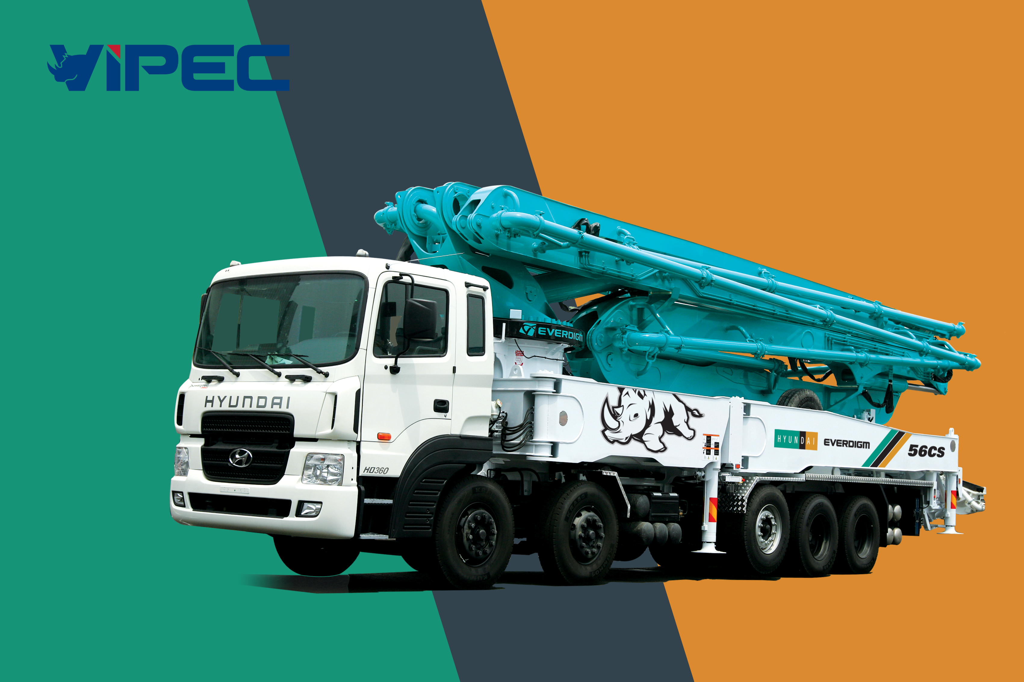
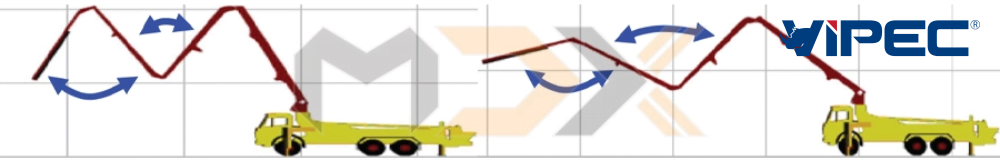
Currently, Everdigm’s boom pump products feature various boom shapes and are compactly folded on Hyundai heavy-duty truck chassis.
Truck-mounted boom pumps are classified by boom length: 00 AB
– 00: Indicates boom length (m). For example, 38 m.
– A: Indicates boom folding type.
– B: Indicates outrigger type.
Typically, A is denoted as R, C, Z and B is denoted as T, S, X:
– R (Roll): Roll folding.
– C (Combine): Combined folding.
– Z: Z-folding shape.
For example, the Hyundai Everdigm 42RX boom pump has a boom length of approximately 42m, a Roll-type boom, and X-style outriggers. Meanwhile, the 60CS boom pump truck has a boom length of approximately 60m, a C-type folding boom, and Square and Swing-out outriggers.
Boom Folding Types
Roll boom
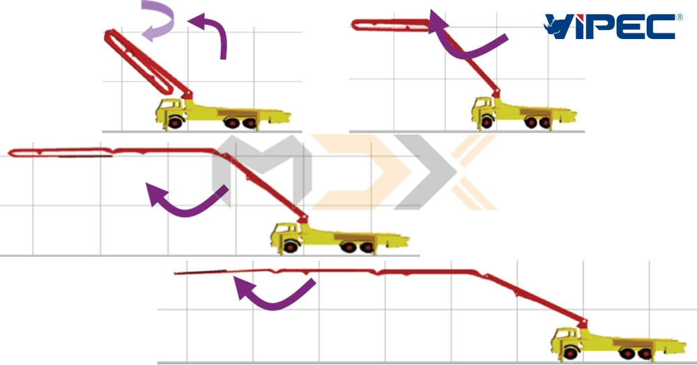
Z boom

Outrigger Types
X-style outriggers
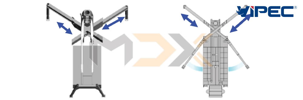
ZX, RX, CX Series
S-style (Swing) outriggers
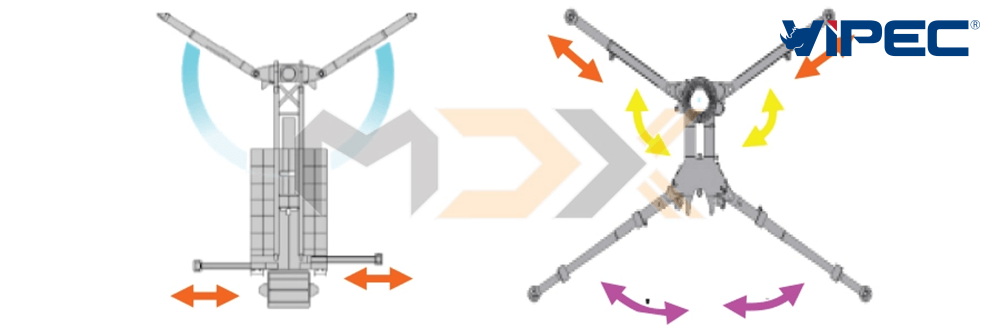
RS and CS Series
Structure of Truck-Mounted Boom Pump
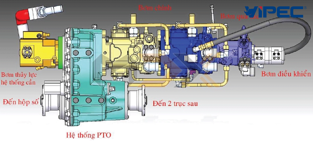
The structure of a boom pump truck includes: a heavy-duty truck chassis with three or more axles. The boom assembly consists of 4 interconnected sections, on which delivery pipes are arranged. Concrete is fed into the hopper. It is then transported to the required position via two cylinders with sequential strokes. The entire hydraulic pump is located after the gearbox and has a separate split-shaft power take-off. The concrete pump control system includes the following components:
– Hydraulic pump engagement unit.
– Direct pump control unit.
– Direct boom control unit.
– Outrigger control unit.
– Wireless remote control.
Hydraulic Pump Engagement System
The task is to transfer drive from the gearbox to the hydraulic pump. When the pump engagement is performed, the base truck loses its mobility, and only the hydraulic pump system remains active. Steps to engage the hydraulic pump:
1. Start the engine.
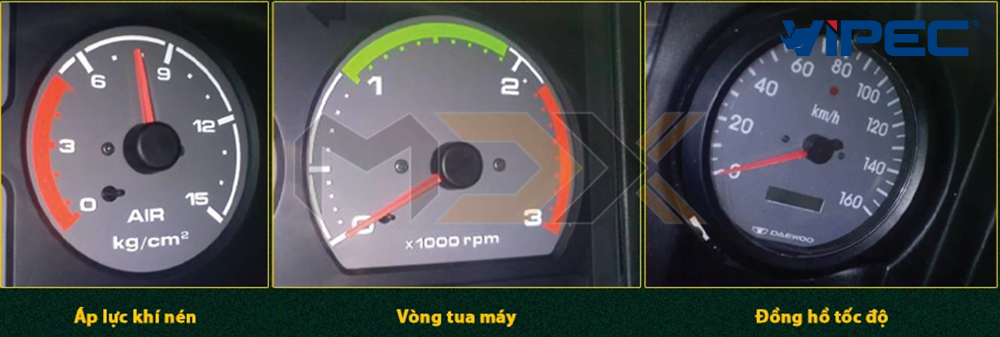
2. Ensure compressed air pressure reaches 6 kgf/cm2 or higher.
3. Press and hold the clutch.
4. Press the PTO switch (hold for 2 seconds) and hear the “beep-beep” signal.
5. Press the pump engagement switch (hold for 2 seconds).
6. Shift to 5th gear.
7. The tachometer will automatically increase RPM.
8. Release the clutch slowly and pump it 3 times. When the speedometer reaches 40km/h, the hydraulic pump is successfully engaged.
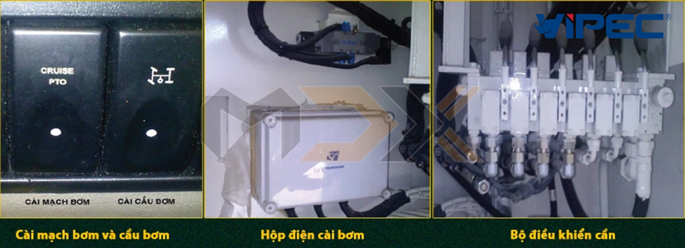
P.T.O: Power Take-Off. Switch for pump control.
HYDRAULIC SYSTEM OF EVERDIGM TRUCK-MOUNTED BOOM PUMPS
Basic Characteristics of Hydraulic Oil
When talking about hydraulic oil, one immediately thinks of its excellent compressibility. With a kinematic viscosity of about 100 to 120 ST and heat resistance up to 2000ºC, plus anti-corrosion properties, its application in force-generating structures brings great efficiency and productivity to the equipment.
Classification of Hydraulic Oil
Hydraulic oil is classified into 3 types according to international standards:
– ISO 32 equivalent to No10 (Gost).
– ISO 46 equivalent to No27 (Gost).
– ISO 68 equivalent to No32 (Gost).
When hydraulic oil is used in heavy industrial environments or heavy-duty equipment, it is designated as HD (heavy duty). ISO 32 is typically used in cold regions with an average annual temperature of 10 – 15 degrees Celsius. ISO 46 is commonly used in subtropical countries (e.g., Vietnam). ISO 68 and ISO 100 are often used in desert environments or harsh hot climates.
Main Technical Specifications of Everdigm Boom Pumps
– Length of boom: The length measured from the center of rotation to the tip of the last section.
– Section of boom: The number of boom segments.
– Vertical reach: The maximum height reached by the boom.
– Horizontal reach: The maximum horizontal distance the boom can extend.
– Depth reach: The depth to which the boom can descend.
– Diameter of delivery pipe: The inner diameter of the two concrete cylinders.
– Slewing range: The limited rotation angle the boom can perform.
– Outrigger: The type of support structure used during operation.
– Max. theo. Concrete output on rod: Concrete flow rate generated on the rod side of the piston.
– Max. theo. Concrete output on piston: Concrete flow rate generated on the piston side.
– Max. theo. Concrete pressure on rod: Concrete pressure generated on the rod side.
– Max. theo. Concrete pressure on piston: Concrete pressure generated on the piston side.
Hydraulic Power Structure of Boom Pumps and LPxxxx Series
Everdigm Concrete Pump Hydraulic Pump
The main pump of Everdigm boom pumps usually uses the Bosch-Rexroth A4VG…HD type. The symbols are as follows: A4VG…HD
– A4: Axial piston type (4-axial).
– V: Variable displacement type.
– G: Closed circuit.
– …: Pump capacity in liters per minute (l/min).
– HD: Heavy Duty.
Example: A4VG 180HD.
This 4-axial variable displacement hydraulic pump operates with a closed-circuit control mechanism, featuring a maximum capacity of 180 liters/minute for heavy-duty power.
The PTO system is used to separate two different independent processes. In the Everdigm boom pump system, the PTO unit connects/disconnects the hydraulic pump system from the driving system.
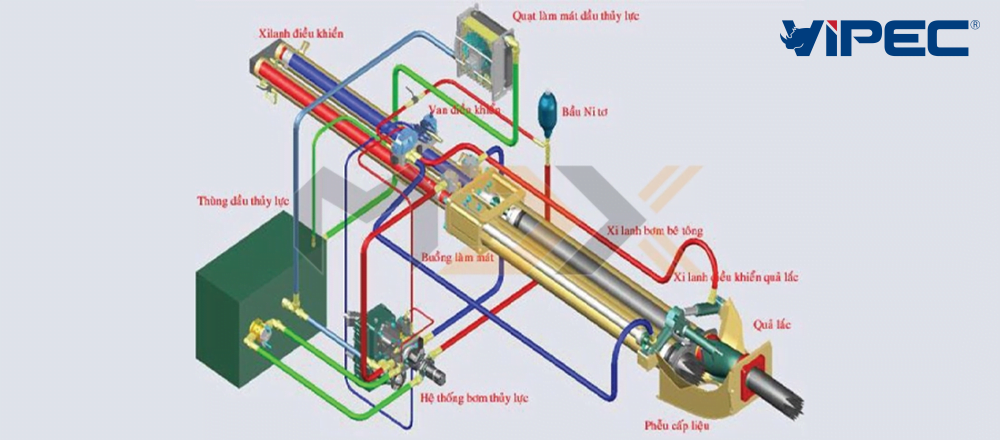
Hydraulic System of Everdigm Boom Pumps
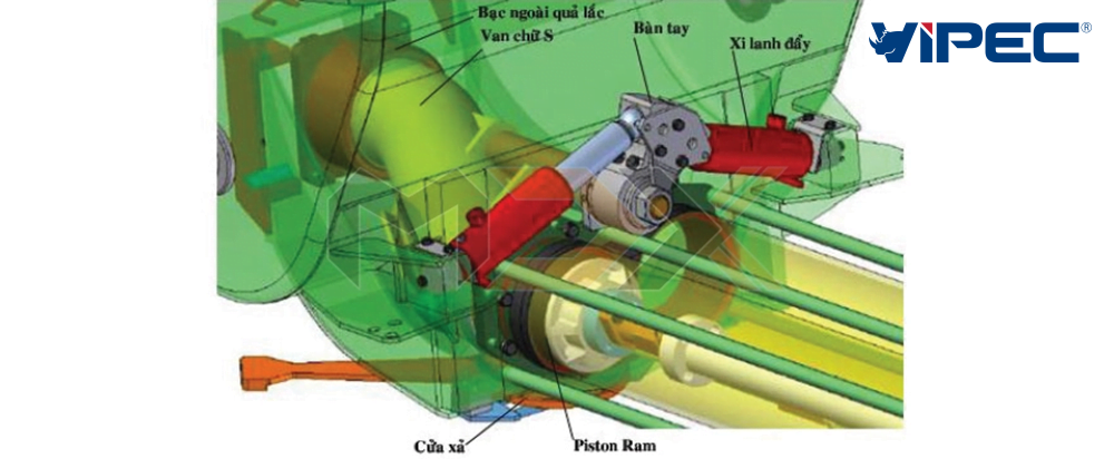
Description of Concrete Pumping Operation
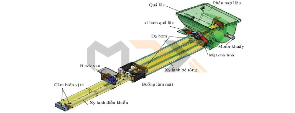
Concrete is poured into the Hopper, where an agitator motor is activated to mix the concrete continuously. When the pump switch on the electrical panel or remote is activated, the solenoid valve opens and supplies hydraulic flow to the S-tube system to switch positions. Simultaneously, one control cylinder sucks concrete into the concrete cylinder, while the other control cylinder forces concrete through the S-tube into the delivery pipe system.
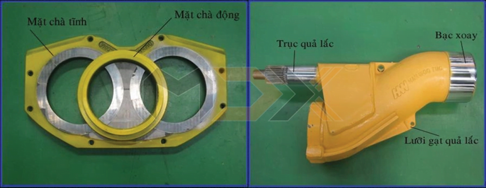
The water tank is where cooling solution (clean water and 0.5 liters of hydraulic oil) is kept to cool the Piston Ram and lubricate the concrete cylinder. Additionally, the water tank is used for replacing the piston rams and monitoring their wear. The wear plate is a silver plate separating the cylinder and the S-tube to create a seal during operation. The wear plate is made of Tungsten Carbide, a hard alloy with high wear and impact resistance.
Everdigm Concrete Pumping System
Pump System Specifications
| Pump Code | Drive Cyl. Dia / Rod Dia (mm) | Stroke (mm) | Concrete Cyl. Dia (mm) | Main Pump A4VG Bosch Rexroth | Output (m3/h) / Pressure (kg/cm2) rod side | Application |
| 1005 | 100/63 | 1000 | 180 | 71HDx1 | 50/30 | TP570 |
| 1409 | 110/63 | 1400 | 200 | 125HDx1 | 90/70 | 24 – 28, LP970 |
| 1609 | 110/63 | 1600 | 200 | 125HDx1 | 90/70 | TP970 |
| 1611 | 140/80 | 1600 | 230 | 180HDx1 | 110/85 | 28, LP1190 |
| 2110 | 160/100 | 2100 | 180 | 180HDx2 | 100/169 | TP1017 |
| 160/90 | 2100 | 200 | 180HDx2 | 100/150 | TP1015 | |
| 140/80 | 2100 | 200 | 125HDx2 | 100/120 | TP1012 | |
| 120/80 | 2100 | 200 | 125HDx1 | 100/70 | 32-37 | |
| 2111 | 160/90 | 2100 | 200 | 180HDx2 | 110/150 | LP1115 |
| 2112 | 140/80 | 2100 | 200 | 125HDx2 | 120/115 | LP1212 |
| 2113 | 120/80 | 2100 | 230 | 125HDx1 | 130/54 | 32-37 |
| 2114 | 130/80 | 2100 | 230 | 180HDx1 | 140/70 | 32 – 40, 43RX |
| 2116 | 140/80 | 2100 | 230 | 125HDx2 | 160/85 | 32-52 |
| 2516 | 140/80 | 2500 | 230 | 125HDx2 | 160/85 | 50-60 |
Note: Specifications are for reference only and are subject to change without notice.
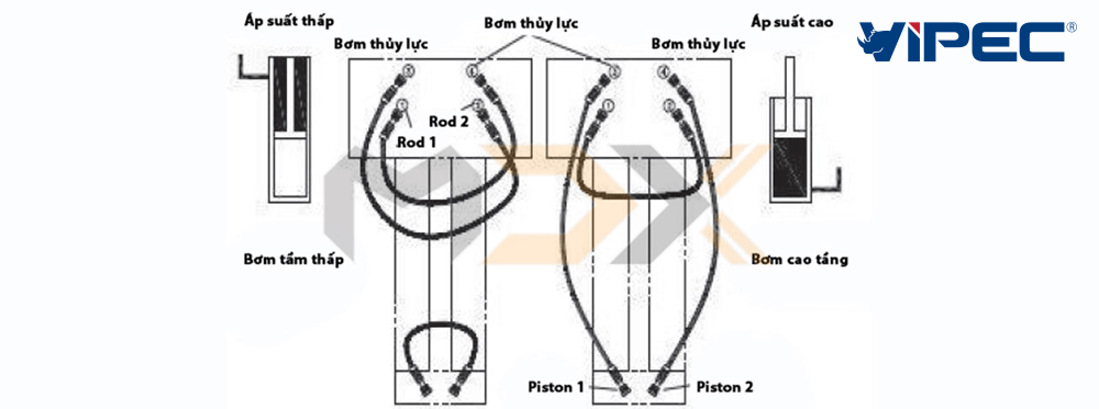
Piston side: Represents the hydraulic oil pressure from the main pump acting on the piston-only part of the control cylinder.
Rod side: Represents the hydraulic oil pressure from the main pump acting on the rod-only part of the control cylinder. Alternatively, this can be understood as the method of connecting the hydraulic pump’s acting line.
If the concrete pump is for buildings taller than 25 floors, it must be switched to the piston side connection and vice versa. This is because the surface area acting on the piston is much larger than the rod, resulting in higher pressure and stronger concrete pushing force.
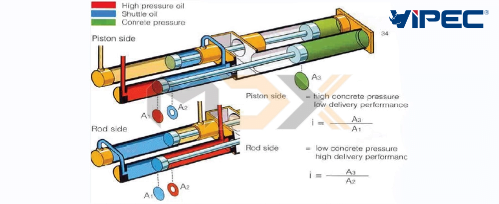
Piston side and rod side
Connection method when pumping for high-rise buildings
Note that when pumping high-rise buildings, the pumping pressure will be higher, but the productivity will decrease.
Concrete Switching Valve System
In the operating principle of concrete pumps, there are many types of switching valves, but the most common is the S-valve (S-tube).
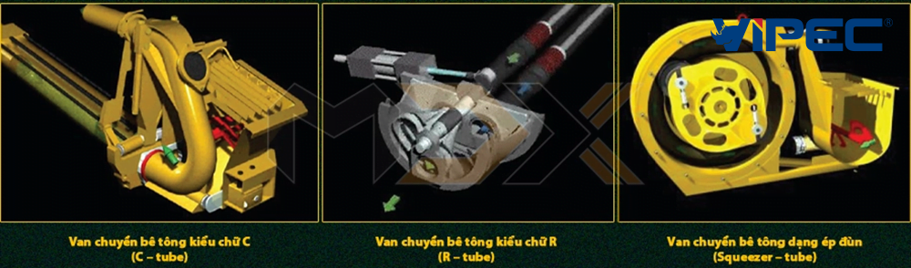
C-tube Valve
Advantages:
+ Compact structure, direct forward push direction.
+ Simple and easy to replace.
Disadvantages:
+ Likely to cause concrete splashing.
+ High output resistance, prone to blockage.
+ Noisy operation and less durable.
R-tube Valve
Advantages:
+ Good concrete mixing ability.
+ Compact structure.
+ Simple hydraulic control system.
Disadvantages:
+ Rare spare parts.
+ Poor concrete pushing productivity.
+ Small hopper capacity.
+ High noise during work.
Squeezer-tube Valve
Advantages:
+ Continuous concrete circulation.
+ Compact structure.
+ Simple hydraulic control system.
+ Can handle low-grade concrete.
Disadvantages:
+ Spare parts are very rare and expensive.
+ Poor concrete mixing ability.
+ Small hopper capacity.
+ High noise during work.
Everdigm’s concrete pump system utilizes the S-valve mechanism, meeting the requirements for operation as well as maintenance and specifically ease of replacement.
Basic Hydraulic Circuit of a Standard Concrete Pump
A basic hydraulic circuit includes the following elements:
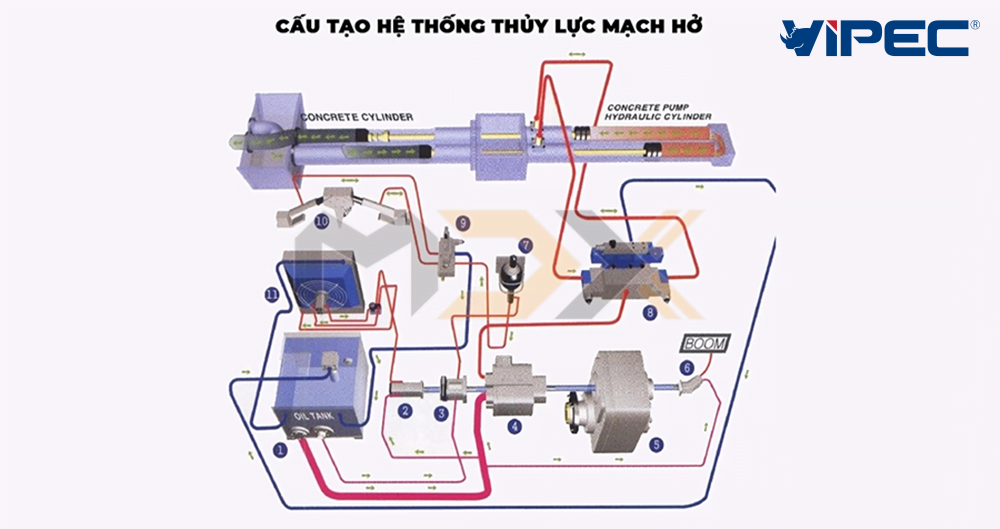
1: Hydraulic oil tank. – 2: Control, outrigger, cooling fan, and water pump hydraulic pump. – 3: S-tube pump. – 4: Main pump. – 5: Pump switching gearbox. – 6: Boom system hydraulic pump. – 7: Accumulator. – 8: Pump cylinder control valve. 9: S-tube control valve. 10: S-tube drive system. 11: Hydraulic oil cooling fan.
Nowadays, many concrete pump manufacturers apply open-loop and closed-loop hydraulic control methods on their equipment.
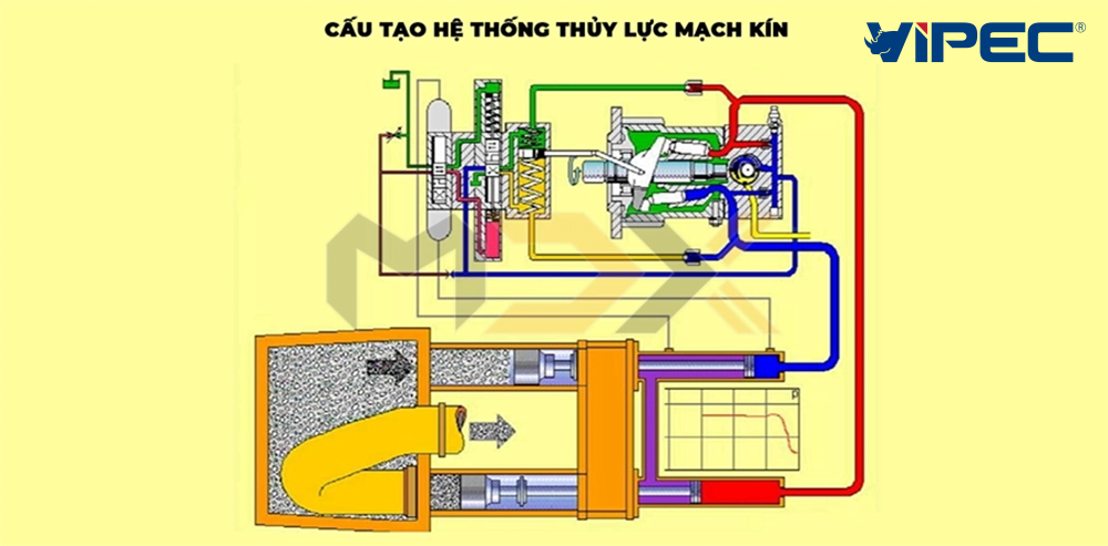
FFH (Free Flow Hydraulic) Closed-Circuit System
HYDRAULIC OIL TANK => MAIN PUMP => CYLINDER => MAIN PUMP
This is the hydraulic cycle applied to the boom pump system of Everdigm pump trucks. The hydraulic oil returns directly from the cylinder to the main pump; only a small amount of oil is diverted back to the tank for cooling.
Open Hydraulic System
HYDRAULIC OIL TANK => MAIN PUMP => CYLINDER => HYDRAULIC OIL TANK
Accumulator and Common Failures
When oil leaves the hydraulic pump, there is always high vibration, causing systems like motors or hydraulic systems to operate unevenly. To avoid this, an accumulator is used in the hydraulic system to create a stable pressure source and desired pressure resonance.
The accumulator consists of a steel shell with a special rubber bladder inside. The rubber bladder is filled with Nitrogen gas (N2) at a pressure of approximately 60 bar to 90 bar.
Properties of Nitrogen Gas
Nitrogen is a colorless, odorless gas with a molecular mass of 14. Nitrogen liquefies at -196°C and solidifies at -210°C. It makes up 78% of the atmosphere’s volume. Nitrogen is non-flammable and non-explosive in high-pressure environments. It only reacts explosively with oxygen when the ambient temperature exceeds 3000ºC.
Furthermore, nitrogen is used as a damper and instantaneous pressure booster. Due to its expansion and inert properties under normal conditions, nitrogen is increasingly popular in both industry and civil use.
In Everdigm’s concrete pump system, the nitrogen bladder is used to stabilize pressure and accelerate the S-tube through a throttle mechanism (tortoise/hare); S-tube pressure is always kept stable at 190 bar. During operation, if the S-tube becomes weak, attention must be paid to the S-tube pressure. If pressure is no longer at 190 bar, stop the machine immediately and check the nitrogen pressure:
+ Use a nitrogen pressure gauge; if the gas pressure is weak, refill nitrogen to 95 bar.
+ Lightly press the valve on the N2 bottle; if hydraulic oil flows out, it confirms the rubber bladder is punctured.
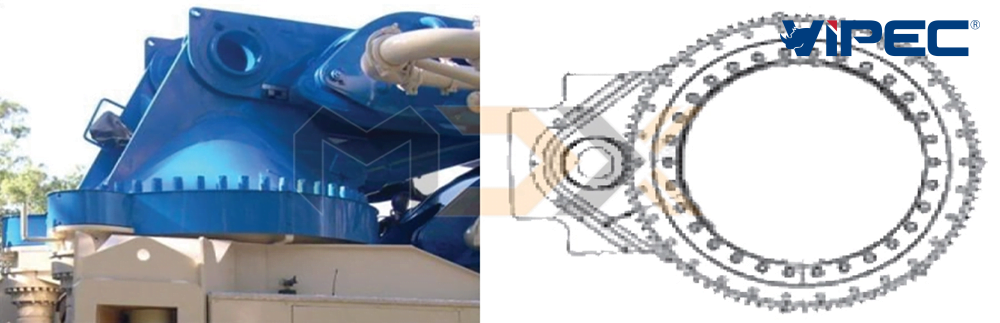
Boom Slewing System
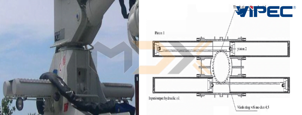
The slewing system is used to change the pumping position around the truck’s rotation center. The system includes a slewing ring with a rack and pinion drive. The movement power comes from 2 cylinders with double strokes creating opposite movement to push the rack, which drives the ring gear to rotate the boom pedestal. The racks and pinions have a module m = 4.5. For boom systems 40m and below, cylinder-type slewing rings are usually used. For trucks longer than 40m, a hydraulic motor slewing unit is used.
Hydraulic motor slewing ring
Note that when slewing the boom in any direction, monitor the boom’s pipeline system, otherwise the pipe may break.
Feeding System (Hopper)
Wireless Control System
During operation, the operator needs to stand in a favorable position for control and observation, making a wireless controller essential for boom pump trucks.
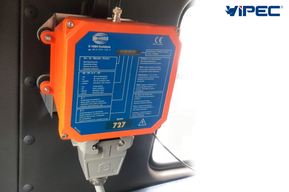
Receiver: 150x150x120mm, mounted in the pump truck cabin
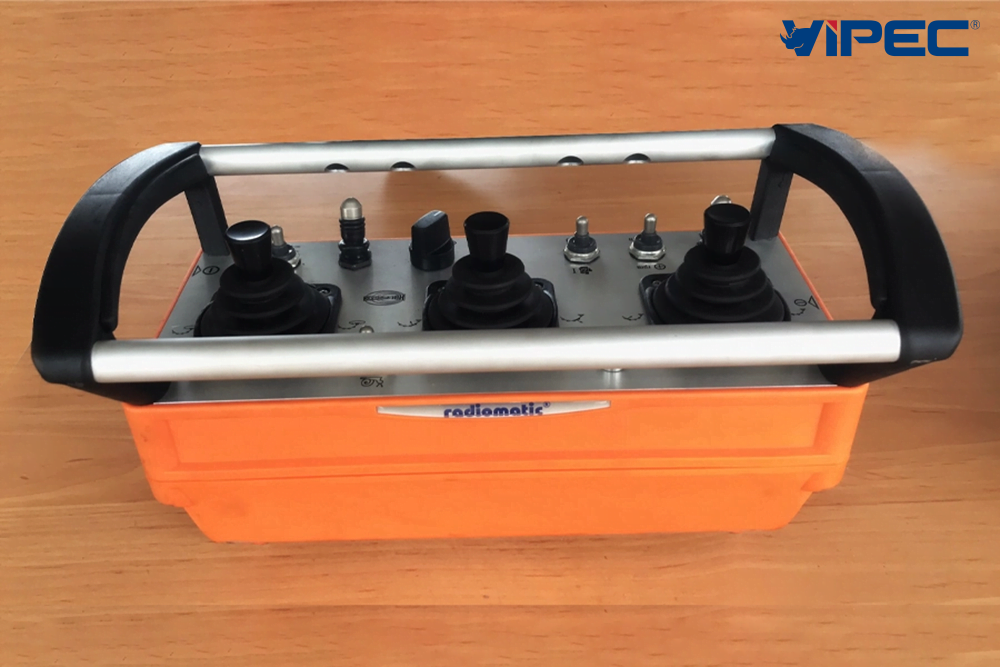
Transmitter: 200x150x120mm, worn on the control technician’s shoulder
The switch buttons on the wireless remote (transmitter) include:
– Horn (reset) and outrigger toggle switch.
– Concrete pumping switch.
– Reverse suction switch.
– Concrete output flow adjustment switch.
– Emergency stop switch for stopping the device or during accidents.
– Tortoise/hare switch for the boom and slewing system.
– Engine start or stop switch.
– Engine speed increase/decrease switch.
– Battery check (uses rechargeable batteries).
– 3rd and 4th boom section extension/retraction switch.
– 2nd boom section extension/retraction switch.
– 1st boom section raise/lower and slewing switch.
Vipec Specialized Equipment Joint Stock Company (a member company of VITRAC) currently distributes a diverse range of boom pump trucks with lengths from 21m to 60m from the Hyundai Everdigm brand. You can refer to the main technical specifications of Hyundai Everdigm boom pumps HERE
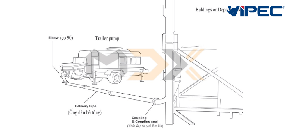
This is a stationary concrete pump fixed at a location on the construction site, responsible for transferring concrete to pouring blocks or combining with a placing boom system. Trailer pumps cannot move on their own and usually require a towing vehicle for relocation.
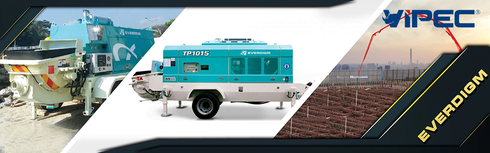
Everdigm trailer pumps are classified by productivity and maximum concrete pressure: TP ABCD
– TP: Trailer pump.
– AB: Indicates pumping productivity (m3/h).
– CD: Indicates pumping pressure (bar).
All ABCD digits represent the productivity and pressure generated on the rod side. For example:
– TP 970: A trailer pump with 90 m3/h productivity and 70 bar pressure.
– TP 1015: A trailer pump with 100 m3/h productivity and 150 bar pressure.
Main Specifications of Trailer Pumps
– Vertical transfer: Pumping height.
– Horizon transfer: Horizontal pumping distance.
– Diameter of delivery pipe: Inner diameter of the 2 concrete delivery cylinders.
– Diameter of Hyd. Driver: Inner diameter of the two hydraulic cylinders.
– Max. theo. Concrete output on rod: Concrete flow rate on the rod side.
– Max. theo. Concrete output on piston: Concrete flow rate on the piston side.
– Max. theo. Concrete pressure on rod: Concrete pressure on the rod side.
– Max. theo. Concrete pressure on piston: Concrete pressure on the piston side.
– Hopper volume: Theoretical capacity of the feeding hopper.
– Water pump pressure: Maximum output pressure of the water pump.
– Accumulator pump: Hydraulic pump for the voltage stabilizer and accumulator system.
You can refer to some main technical specifications of Everdigm trailer pumps currently distributed by Vipec HERE
The applicability of trailer pumps is very diverse. In large projects like complexes or building groups, trailer pumps work very effectively. In those areas, people often arrange multiple pump locations with a pipeline system. As construction goes higher, the pipeline assembly develops. When a building exceeds certain limits, a Placing Pump combined with a trailer pump is used for greater versatility and mobility.
For high-rise building construction, a shut-off valve is often used at the transition point of the pipeline from the ground to the height (at the 90-degree bend) to prevent concrete from flowing back in case of pump failure.
Standard Trailer Pump Spare Parts for 100m Height
| No. | Type | Specification | Quantity |
| 1 | Concrete pipe 3m type | DN125 x 3000 | 33 |
| 2 | Concrete pipe 2m type | DN125 – 2000L | 2 |
| 3 | Concrete pipe 1m type | DN125 – 1000L | 2 |
| 4 | High-pressure pipe clamp | 5.5′ | 48 |
| 5 | Seal (5.5′ / O-RING) | High pressure | 48 |
| 6 | 90-degree elbow | 125 – 1000R – 90′ | 3 |
| 10 | 45-degree elbow | 125 – 1000R – 45′ | 2 |
| 11 | 15-degree elbow | 125 – 1000R – 15′ | 2 |
| 12 | Cleaning ball | 125 | 10 |
| 13 | Shut-off valve | 2-way | 1 |
| Total | 151 | ||
Note: Specifications are for reference only and are subject to change without notice.
Pipes come in 2 different types. If used for the TP970 series, lever clamps with rubber seals are used. If for TP1012 to TP1015 series, nut-tightened clamps with O-rings are used.
Additionally, DN125 is the standard pipe size, but DN150 can also be used.
When pumping concrete, rotating joints are often used for convenience. The method involves using two 90-degree elbows with R500 connected to create a flexible rotation angle. Note that when constructing, pipelines must be fixed tightly and leaned against columns or beams; avoid connecting pipes at column necks as vibrations can affect the building’s structure.
Regarding the end hose, absolutely do not attach rubber hoses; this is dangerous because the outlet releases a large accumulated pressure. When pressure is released suddenly, it causes hose whipping, which can lead to unexpected accidents.
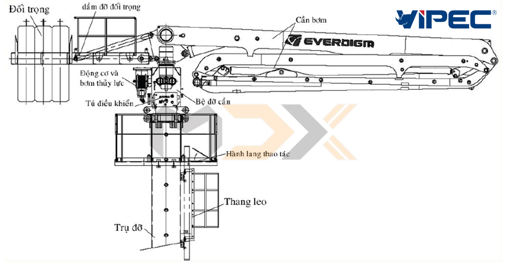
This is an auxiliary equipment for concrete construction. It consists of a supporting mast, on top of which is the pedestal and the boom of a boom pump. The system is stabilized by a rear counterweight. During operation, the boom can rotate 370 degrees around its axis.
It is powered by a 3-phase 380V AC power source dedicated to the boom system, achieving high stability during work.
Placing Boom Code: PB xy -z
– PB: Placing boom.
– xy: Boom length.
– z: Number of boom sections.
Example: PB 32 – 4 means a placing boom with 32m length and 4 sections.
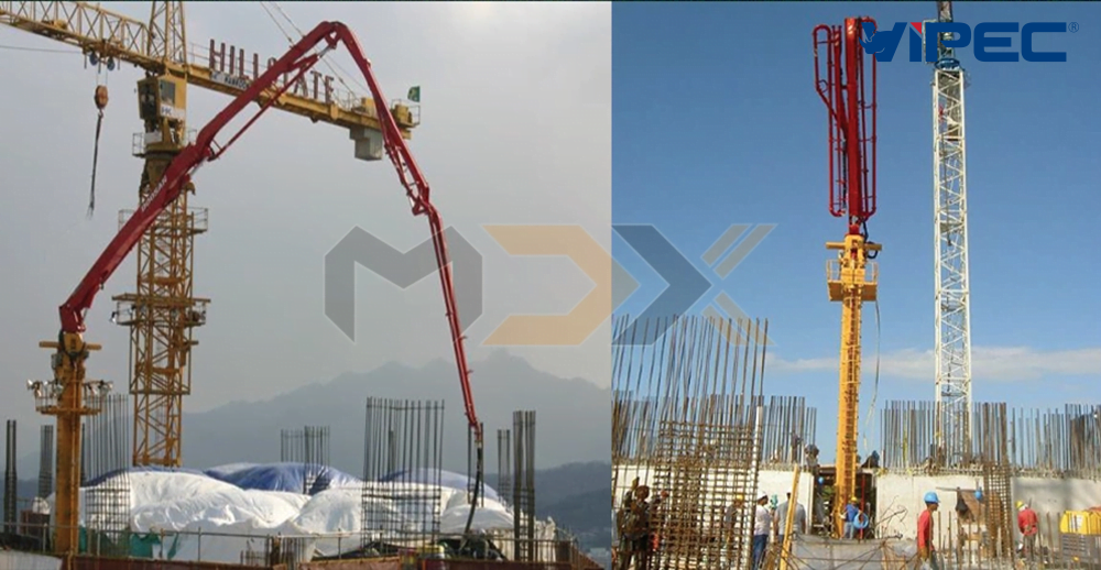
When installing a placing boom, people often use elevator shaft spaces. Once the building foundation is done, the foundation for the placing boom is built, and its mast is installed. As the building rises, the placing boom moves up with it. To lift the system, a hydraulic cylinder is used to raise the mast in 1m increments. The mast is fixed to concrete floor slabs or edge beams using special mounting systems. Note that installing and dismantling a placing boom requires a tower crane with 15t capacity or more.
Parts of a Concrete Placing Boom
| Features | Unit | Model – PB32 |
| Boom Type | – | 4-section Roll Boom, 32m |
| Horizontal Reach | m | 32 |
| Working Depth | m | 24 |
| Concrete End Hose | m | 3 |
| Mast Length | m | 20 (10m x 2) |
| Slewing Angle | ˚ | 370 |
| Power Source | V / Hz | 380 / 60 (STD) – 380 / 50 (Option) – 440 / 50 (Option) |
| Remote Control System | – | Cable Remote Control |
| – | Radio Remote Control | |
| Boom Weight | Kg | 5,800 |
| Pedestal Weight | Kg | 2,500 |
| Mast Weight | Kg | 3,300 x 2 |
| Counterweight + Frame | Kg | 6,900 (6,300 + 600) |
Note: Specifications are for reference only and are subject to change without notice.
Accessories for Concrete Placing Booms
| No. | Name | Unit | PB32 |
| 1 | Boom without pedestal | pcs | 1 |
| 2 | Pedestal | pcs | 1 |
| 3 | Main Mast (750mm x 750mm x 10,000m) | pcs | 2 |
| 4 | Mast fixing frame | pcs | 3 |
| 5 | Mast pin | pcs | 2 |
| 6 | Remote controller | pcs | 1 |
| 7 | Cable Remote Control with 40m cable | pcs | 1 |
| 8 | Concrete outlet hose – 3m | pcs | 1 |
| 9 | Mast lifting cylinder | pcs | 1 |
| 10 | Hydraulic hose | pcs | 1 |
| 11 | Lifting control unit | pcs | 1 |
| 12 | Converter | pcs | 1 |
| 13 | Operating platform | pcs | 1 |
| 14 | Ladder | pcs | 1 |
| 15 | Concrete counterweight | pcs | 3 |
| 16 | Counterweight frame | pcs | 1 |
| 17 | Bolt and nut (M30X400) | Set | 1 |
| 18 | Spare parts | Set | 1 |
Note: Specifications are for reference only and are subject to change without notice.
The device always requires a 3-phase power source. If no grid power is available, a generator must support it. The device excels when combined with a TP1015 trailer pump or higher, or the LP1212 series. In high-rise projects, people often install a continuous series of 4 or more placing booms to shorten construction time and ensure concrete quality.
In modern construction technologies like Slip-form, applying this pumping system achieves rapid progress. However, the downside is the expensive mast support system, so PB application in this tech in Vietnam remains limited.
Everdigm Placing Boom Models
| Name | Unit | EPB 28 | EPB 32 | EPB 36 | EPB 42 |
| Boom | |||||
| Boom Type | – | 4 – R Boom | 4 – R Boom | 4 – R Boom | 4 – R Boom |
| Horizontal Reach | m | 28 | 32 | 36 | 42 |
| Working Depth | m | 21 | 24 | 29 | 27 |
| Outlet Hose | m | 3 | 3 | 3 | 3 |
| Combination | |||||
| Mast Height | m | 20 (10m x 2EA) | 20 (10m x 2EA) | 20 (10m x 2EA) | Tower mast |
| Option: Tower mast | Option: Tower mast | Option: Tower mast | |||
| Power Source | V / Hz | 380 / 60 | 380 / 60 | 380 / 60 | 380 / 60 |
| 380 / 50 (Option) | 380 / 50 (Option) | 380 / 50 (Option) | 380 / 50 (Option) | ||
| 440 / 50 (Option) | 440 / 50 (Option) | 440 / 50 (Option) | 440 / 50 (Option) | ||
| Weight | |||||
| Boom Weight | Kg | 5,000 | 5,800 | 5,300 | 5,000 |
| Pedestal Weight | Kg | 2,500 | 2,500 | 5,000 | 11,000 |
| Counterweight & Frame | Kg | 2,500 (2,100 + 400) | 6,900 (6,300 + 600) | 13,300 (12,000 + 1,300) | 14,400 (10,500 + 3,500) |
Note: Specifications are for reference only and are subject to change without notice.
Method for Raising the Entire Stationary Pump
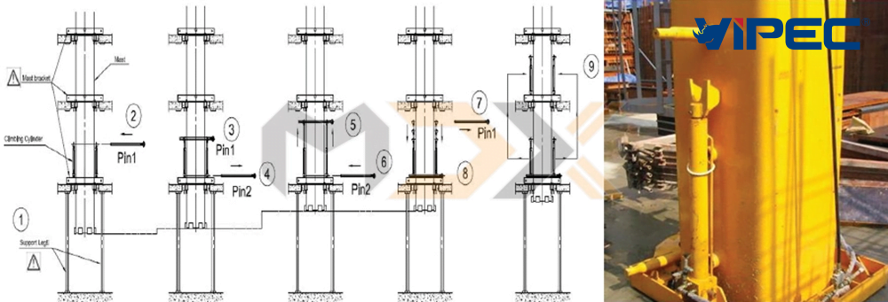
Step 1:
+ Prepare the mast lifting system. Check the hydraulic pump control power source.
+ Check around and the mast body.
+ Start the hydraulic pump and switch the lift control via remote.
Step 2: Insert Pin 1 into the mast at the lift cylinder position.
Step 3: Engage the safety latch.
Step 4: Remove Pin 2 from the Bracket.
Step 5: Proceed to lift the mast to the required position (1m).
Step 6: Insert Pin 2 into the Bracket.
Step 7: Remove Pin 1.
Step 8: Retract the lifting cylinder.
Step 9: Move the lifting system up to the next floor and repeat the cycle.
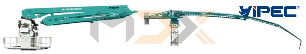
Combination of Placing Boom with Trailer Pump or Line Pump and Distribution Equipment
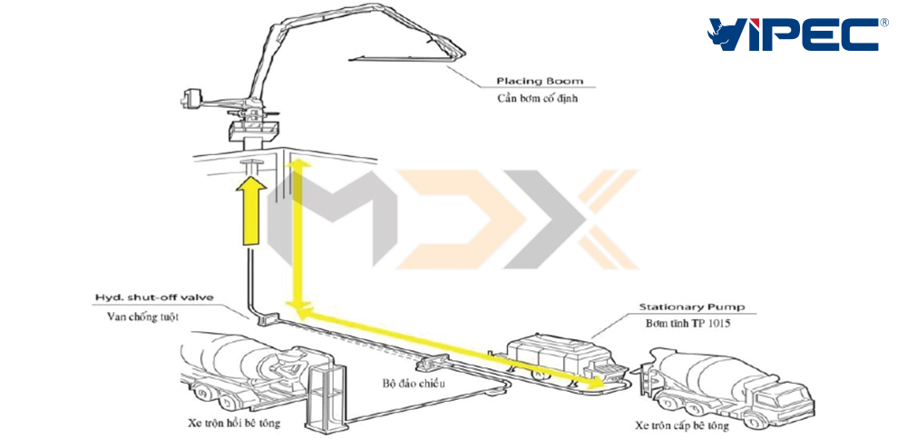
During operation, concrete is delivered by a mixer truck. The trailer pump is responsible for pushing concrete up to the placing boom. The active placing boom will pump concrete to necessary locations. When work is complete, due to the building’s height, a large volume of concrete remains in the pipeline. At this point, reverse suction cannot be performed; instead, the gravity method is used:
– Position the mixer truck at the delivery pipe inlet, then open the reverse switching valve. Now the placing boom pipeline system is connected to the mixer truck. Concrete from above, due to gravity, will flow into the mixer truck. When the truck is full, the valve is switched back, stopping the flow. The truck transports the concrete away, and another truck takes its place to continue until the pipeline is empty, from which point the trailer pump performs the remaining cleaning.
Note: Like the trailer pump, this system also has a safety component called the shut-off valve, which is indispensable.
Replacement schedule for spare parts:
– After pumping over 2,000 m3: replace pipe elbows.
– After pumping 5,000 m3: replace piston rams.
– After pumping 8,000 m3: replace dynamic and static wear plates.
– After pumping 12,000 m3: replace S-tube shaft bearings (front and rear).
– Every 30,000 m3: replace S-tube and hydraulic cylinder seals.
TECHNICAL MAINTENANCE OF CONCRETE PUMPS
General Regulations
Technical maintenance of concrete pumps includes daily and periodic inspections such as: bolt tightening, lubrication, oil changes, and adjustment of concrete pump mechanisms for both new and old machines. Maintenance tasks are divided as follows:
– Technical maintenance when preparing the machine for use, during and after the first 50 hours of operation for new machines.
– Performance of mandatory (or periodic) technical maintenance requirements.
– New concrete pump maintenance tasks are also performed simultaneously.
– Maintenance tasks upon request will be performed depending on instrument readings, signals, and specific signs of technical status. These tasks are conducted based on after-shift maintenance principles. Periodic maintenance tasks will be performed without pre-checking the machine status. For concrete pumps, the periodic technical maintenance types are:
– ETM: technical maintenance performed every shift or every running hour.
– TM 1: after every 50 running hours.
– TM 2: after every 250 running hours.
– TM 3: after every 1,000 running hours.
– STM: Season technique maintenance performed during seasonal changes.
– Transition from autumn-winter to spring-summer (when ambient temperature is between -5 and +5°C, usually in cold climates).
– Transition from summer to autumn-winter (when ambient temperature starts falling below +5°C).
Seasonal maintenance can be done with one of the TMs when using concrete pumps under special conditions (heavy dust, gravel, swampy ground, low temperature, steep hills), where additional maintenance is performed.
DO NOT OPERATE CONCRETE PUMPS WITHOUT COMPLETE AND PERIODIC TECHNICAL MAINTENANCE AS REGULATED.
Depending on working conditions, periodic maintenance times TM1 and TM2 can shift by 10%, and TM3 by 5%.
After-shift maintenance and periodic maintenance TM1 and TM2 can be performed at the job site on a clean, fire-safe open space.
Seasonal maintenance is performed in a covered workshop where rain and dust do not affect the pump. Cleaning and refilling (fuel, antifreeze) must be done carefully to avoid contamination or spills.
When draining waste oil from systems and components, containers (buckets, pans) must be used; do not let oil spill on the floor (ground).
Cleaning materials must be collected and stored separately after work.
Used oil must be kept in specialized containers for recycling.
Diesel fuel, kerosene, or gasoline used for cleaning parts must not be discarded or mixed; store them in separate containers for settling and potential reuse.
Bolt tightening with specific torque must be done with a torque wrench.
Technical maintenance for new machines:
Applied to equipment used for the first time:
+ Check synchronization and re-install parts removed during transport or storage.
+ Remove external preservation layers, clean off protective grease and paraffin paper.
+ Check levels of engine oil and hydraulic oil; refill if necessary.
+ Pay attention to the Engine Crankcase.
+ Gearbox Crankcase.
+ Cooling system – use cooling solution (clean water in Vietnam).
+ Check radiator and hydraulic cooling tank.
+ Check battery and electrical system.
+ Check boom system.
+ Check piston ram cooling system.
+ Check S-tube system + wear plate and automatic lubrication.
Check by external observation for connection reliability between components, ensuring no leaks of fuel, oil, or coolant; tighten or fix leaks if found.
* Note: after starting, immediately observe the dashboard gauges (charge, engine oil pressure, water temperature, hour meter…); if any gauge is inactive, report to the Manufacturer/Supplier immediately for replacement.
After 50 operating hours, conduct maintenance and change engine oil and gearbox oil (both mechanical and hydraulic gearboxes). After 50 hours, engine oil should be 15w/40; hydraulic gearbox oil should be VG46 (GS brand). When changing oil, clean the oil reservoir thoroughly and replace filters.
Legend:
– ETM1: performed during the first 50 machine hours => Full maintenance. Change engine and gearbox oil and all filters. Use correct filters and oil as regulated.
– TM2: performed every 250 machine hours => Full maintenance. Change engine and gearbox oil and all filters.
– TM2 bs: performed every 500 machine hours => Full maintenance.
– TO-3: performed every 1,000 machine hours => Full maintenance.
– TO-3 bs: performed every 2,000 machine hours => Full maintenance. Change engine, gearbox, and hydraulic oil and all filters.
Compiled by – Nguyen Anh Long

03-2026

03-2026
06/03/2026

12-2025

12-2025

11-2025